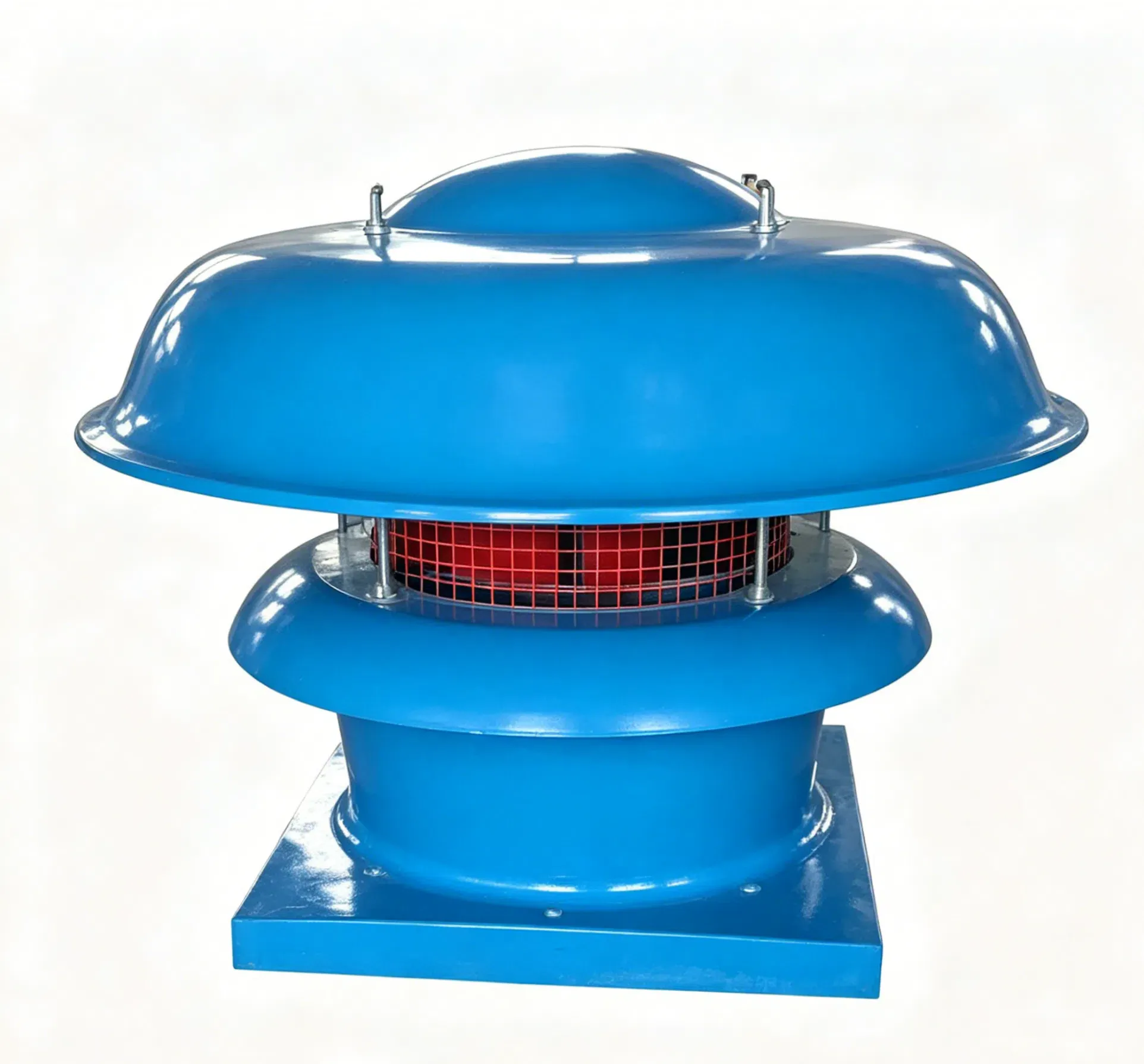


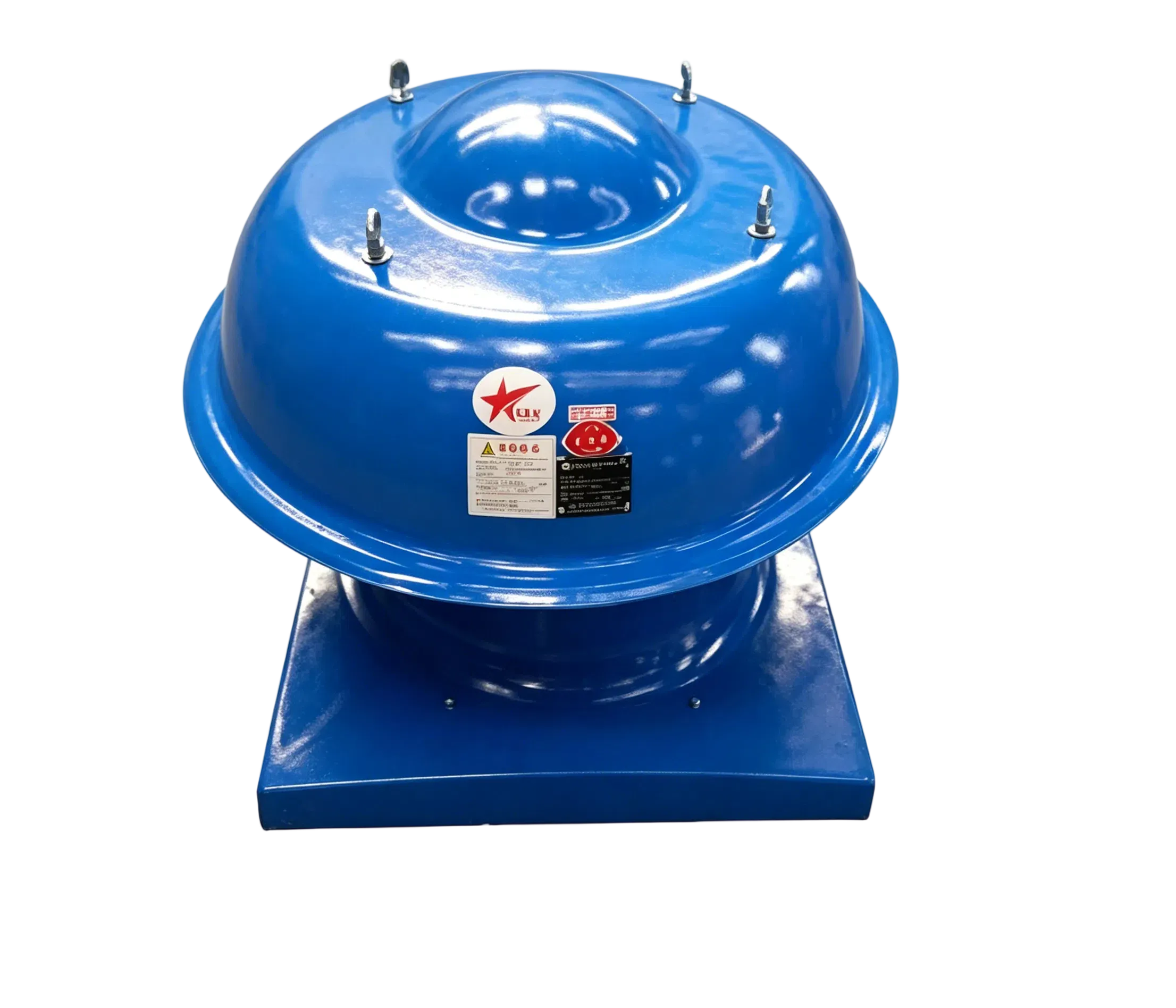
Product Details
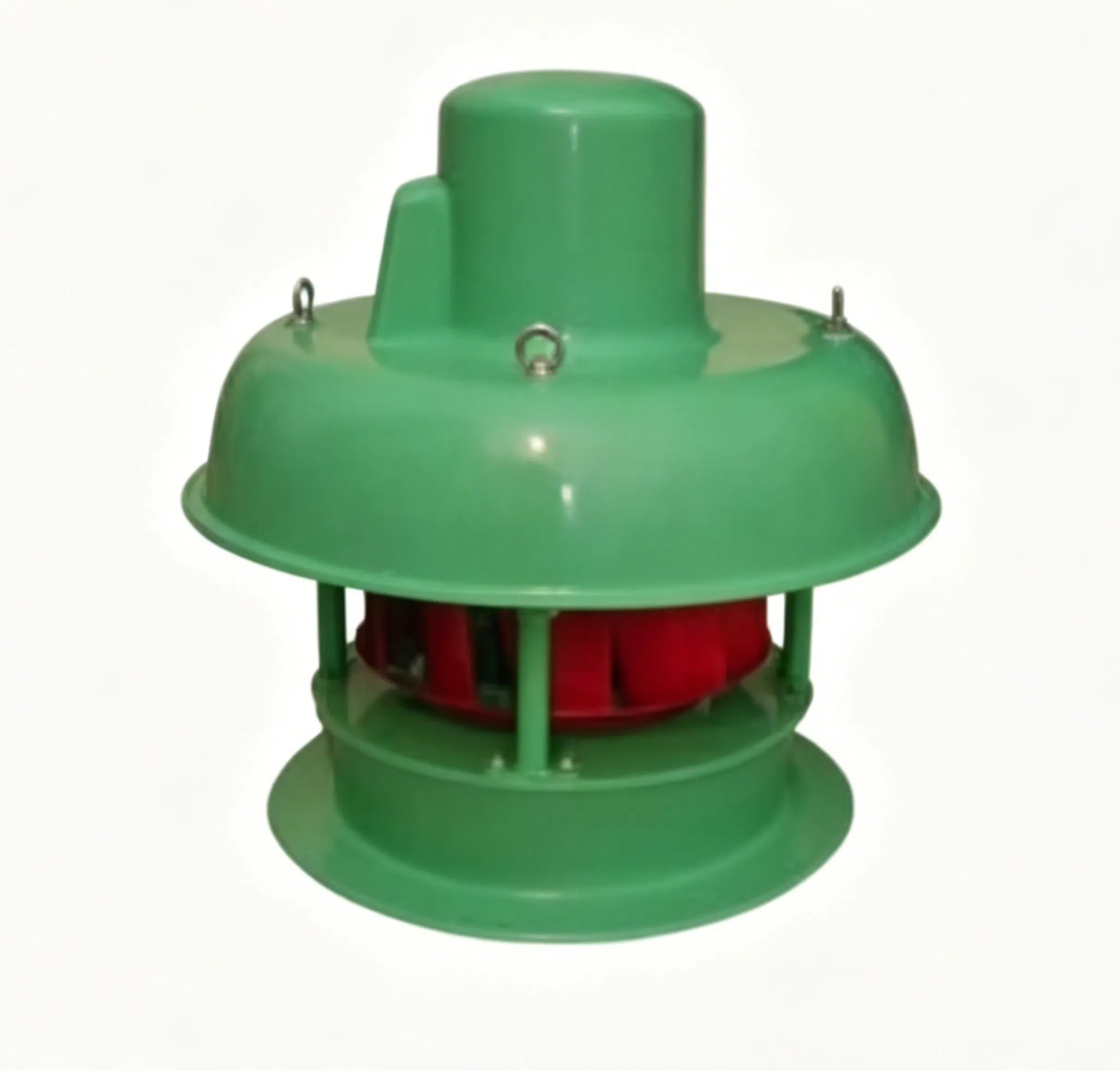
The DWT‑series axial‑flow roof fan features wide twisted inclined blades to reduce noise during low‑speed operation. It has 17 specifications with wide air volume and pressure range, and models No.12 and above adopt adjustable blades for energy‑saving and noise reduction. Equipped with two‑speed or variable‑frequency speed regulation, it adapts to different working‑condition demands. Available in standard, explosion‑proof and anti‑corrosion types, it stably operates at ‑20℃‑+40℃ with humidity below 90%, suitable for various ventilation occasions. With precisely balanced impeller and integrally‑formed shell, the fan has reliable structure and complete configurations, meeting diversified application requirements.
Performance Parameter Table
This table shows performance parameters of DWT‑I axial‑flow roof fan, covering No.3‑7 with multiple rotating speeds including 2850, 1450, 960, 720 and 560 r/min. It features wide ranges of air volume and total pressure, power from 0.04 to 1.5 kW and noise of 51‑73 dB(A). Complete supporting motor models are provided to meet requirements of air volume, pressure, noise reduction and energy‑saving operation in various ventilation scenarios. We also have other models of the same series, and there is always one suitable for you.
| No. | Speed(r/min) | Air Volume(m³/h) | Total Pressure(Pa) | Motor Model | Power(kW) | Noise dB(A) |
| 3 | 2850 | 3300 | 181 | 711‑2 | 0.37 | 66 |
| 3000 | 206 | |||||
| 2600 | 232 | |||||
| 1450 | 1650 | 62 | 561‑4 | 0.06 | 52 | |
| 1560 | 66 | |||||
| 1450 | 72 | |||||
| 1450 | 1100 | 25 | 502‑4 | 0.04 | 51 | |
| 950 | 32 | |||||
| 800 | 37 | |||||
| 4 | 2850 | 7450 | 193 | 801‑2 | 0.75 | 69 |
| 6350 | 230 | |||||
| 5300 | 250 | |||||
| 1450 | 5700 | 176 | 801‑4 | 0.55 | 67 | |
| 5400 | 184 | |||||
| 4580 | 190 | |||||
| 960 | 3800 | 69 | 712‑6 | 0.25 | 62 | |
| 3400 | 80 | |||||
| 3000 | 85 | |||||
| 5 | 1450 | 8000 | 135 | 801‑4 | 0.55 | 68 |
| 7000 | 162 | |||||
| 5600 | 191 | |||||
| 960 | 7000 | 113 | 801‑6 | 0.37 | 63 | |
| 6700 | 122 | |||||
| 6400 | 131 | |||||
| 720 | 6000 | 88 | 802‑8 | 0.25 | 58 | |
| 5000 | 92 | |||||
| 4100 | 96 | |||||
| 6 | 1450 | 15000 | 232 | 90L‑4 | 1.5 | 73 |
| 14000 | 251 | |||||
| 13000 | 267 | |||||
| 960 | 11000 | 168 | 90L‑6 | 1.1 | 67 | |
| 10000 | 183 | |||||
| 9100 | 193 | |||||
| 720 | 8500 | 111 | 90L‑8 | 0.55 | 62 | |
| 8000 | 127 | |||||
| 7600 | 136 | |||||
| 7 | 960 | 17500 | 165 | 100L‑6 | 1.5 | 69 |
| 15000 | 201 | |||||
| 12500 | 212 | |||||
| 720 | 12000 | 141 | 100L1‑8 | 0.75 | 63 | |
| 11000 | 163 | |||||
| 9200 | 177 | |||||
| 560 | 9300 | 83 | 90L‑10 | 0.55 | 59 | |
| 8500 | 94 | |||||
| 7200 | 102 |
I. Applications of DWT‑I Axial‑Flow Roof Fan
It is suitable for ventilation and air exchange in medium‑low pressure and large‑flow sites such as warehouses, industrial plants, power stations, stations and gymnasiums.
II. Configuration of DWT‑I Axial‑Flow Roof Fan
Standard Configuration
Impeller, Fan Housing (outer cylinder, motor bracket), Motor, FRP Wind Cap, Safety Net
Spare Parts & Accessories (Please specify purchase requirement when ordering)
Manual or Electric Regulating Valve, Control Box, Gravity Louver, Bird‑proof Net
III.Processing Technology of DWT‑I Axial‑Flow Roof Fan
The fan impeller is made of steel or FRP. The cross frame is stamped and hydraulically formed from steel materials. Blades are hydraulically formed after aluminum alloy stamping, and riveted to the cross frame for assembly. The impeller undergoes static and dynamic balance correction with a balance accuracy not higher than Grade G5.6.
The outer cylinder flange is integrally formed by edge‑turning and spinning. The wind cap is one‑shot molded from FRP. The fan housing of explosion‑proof and anti‑corrosion explosion‑proof types is one‑shot molded from FRP.
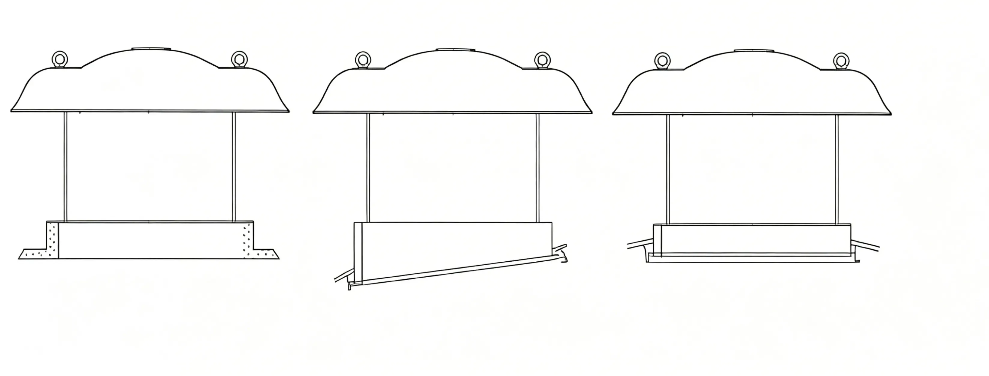
Overall and Installation Dimensions
This table presents the overall and installation dimensions of DWT‑I axial‑flow roof fan from No.3 to No.11.2, including key parameters such as diameter, height, base frame size, anchor bolt specification and unit weight. Dimensions increase progressively with model numbers, and weight rises accordingly, providing direct guidance for equipment selection, roof foundation pre‑embedding and on‑site installation.
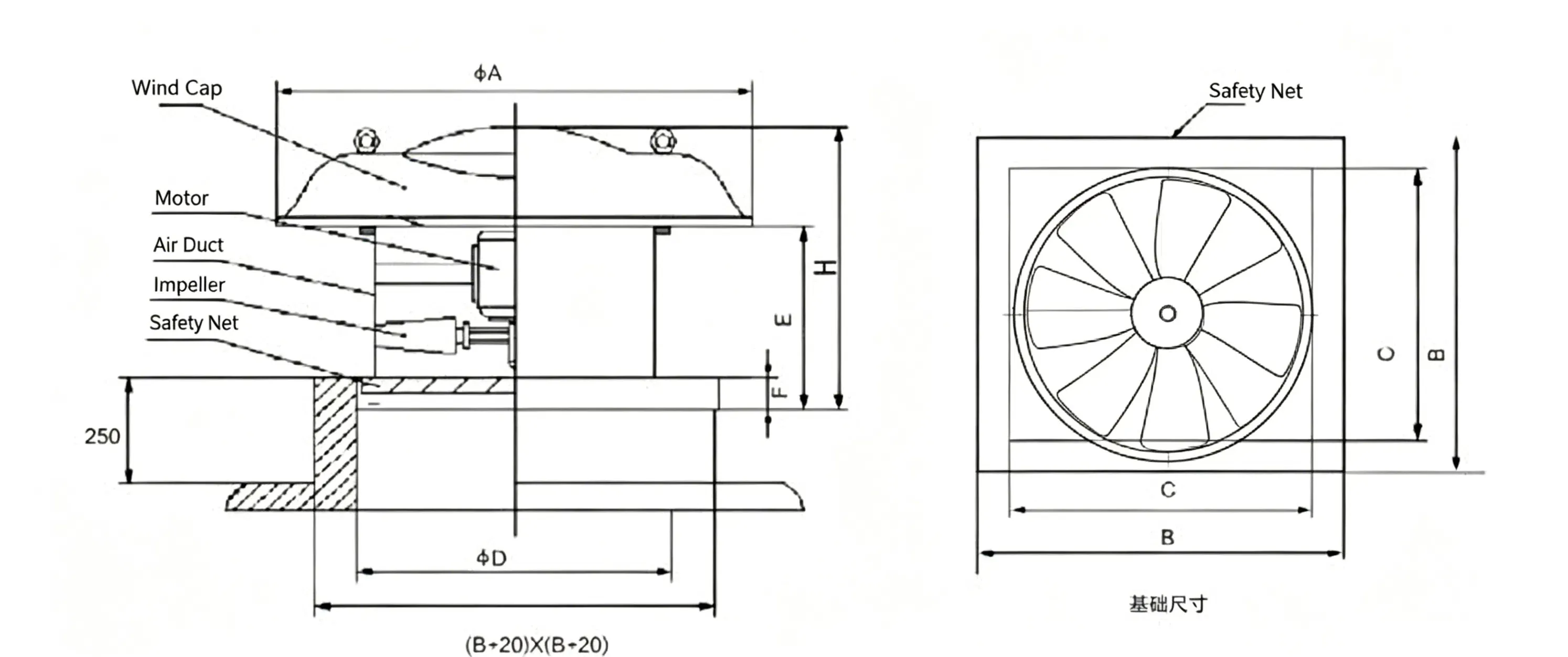
| No. | ΦA | ΦD | F | G | E | Base Frame Dimension‑B | Base Frame Dimension‑C | H | M(d)*L | Weight(kg) |
|---|---|---|---|---|---|---|---|---|---|---|
| 3 | 650 | 310 | 60 | 30 | 300 | ≤510 | ≥370 | 545 | 10.5*100 | 11 |
| 4 | 650 | 410 | 60 | 30 | 340 | ≤630 | ≥470 | 585 | 10.5*100 | 20 |
| 5 | 890 | 510 | 60 | 30 | 390 | ≤750 | ≥570 | 715 | 10.5*100 | 26 |
| 6 | 1000 | 610 | 60 | 30 | 440 | ≤870 | ≥670 | 765 | 12.5*120 | 41 |
| 7 | 1220 | 710 | 80 | 40 | 480 | ≤1000 | ≥800 | 950 | 12.5*120 | 62 |
| 8 | 1340 | 810 | 80 | 40 | 480 | ≤1100 | ≥900 | 950 | 12.5*120 | 90 |
| 9 | 1650 | 910 | 80 | 40 | 480 | ≤1250 | ≥1000 | 950 | 12.5*120 | 105 |
| 10 | 1650 | 1010 | 80 | 40 | 480 | ≤1400 | ≥1100 | 1105 | 12.5*150 | 155 |
| 11.2 | 1800 | 1130 | 80 | 40 | 480 | ≤1540 | ≥1240 | 1105 | 12.5*150 | 186 |